Tuesday, August 23, 2016

Let there be light!

Today was spent fitting the lights, now the car really starts looking like a Caterham!

Crimp type bullet connector used instead, not sure about the blue though. Nice toes...
First off was the number plate light (see above), a simple task, the wire provided was way more than needed, so it was cut down to size. We're thinking that in the future of converting to LEDs, so left a little extra for re-wiring, if required. The only problem we had was that the bullet connector provided turned out to be a solder not a crimp-type (against what the Assembly Guide said), so split when I tried to squeeze it together. Fortunately I had some in my aero-modelling toolbox - potential disaster averted - however the blue insulation is somewhat conspicuous.

Pre-drilled 30mm hole (wiring) and a 4mm hole for the mounting screws.
Next up was the rear lights, again a relatively simple task. The rear wings come pre-drilled with a 30mm hole and one of the four 4mm holes required to mount the rear light assemblies (above), we used a screw to attach the assembly and a spirit level to make sure everything was level.

Mounting the left hand rear light assembly using the provided self-tapping screws. Not our first choice...
Then it was a case of drilling the other 3 holes and screwing them in (above). We have to say that the use of self tapping screws was not our first choice, they're a little crude and it cracks the fibreglass. Also, it makes a horrible cracking noise when you tighten them, we would have much preferred to have used bolts. We may come back and revisit this once the IVA is complete.

Rear lights fitted.
The front lights and indicators were relatively straightforward also, first off you have to add IVA strip around the mounting cone then mount the indicators to them, see below. 

Front indicator and mounting cone. Note the IVA strip.
Next up it was taking the front lens off the light and getting to the headlight bowl (see below).

Front lens assembly and headlight bowl.
This was so that after you pass the headlight mounting stud through the indicator cone and into the headlight bracket you can then pass the black indicator earth wire back up inside the thread and mount it inside the headlight bowl. And breathe, gottit?

The black indicator earthing wire heading up the thread to mount inside the headlight bowl.
This was repeated for both sides and a big part of the car's identity had started to come together; it started to look like a Caterham!

Front lights fitted, big part of the car's identity!
The wiring for the headlights and indicators pass through a hole into the headlight mounting bracket and reappears inside the body, where it is connected to the loom via a connector block. Routing the wiring though this hole was somewhat fiddly to achieve. We inserted the individual wires into the connector block later, as we had to include the wiring for the repeater lights (on the cycle wings). 

Wiring from the repeater into the cycle wing support, note the heat-shrink.
The repeater light wiring was a bit of a bugger to route into the car, the holes were quite small in the cycle wing supports (above) and getting the connector out near the brace was a bit of pain, to say the least (see below). Part of the problem was of our own making; we chose to lengthen the earth wire and mount it inside the chassis, rather than on the wing-stays themselves, meaning that the space available inside the tube was reduced, however we feel that the extra time spent was worth it.

Bit of a pain getting the wiring out of the hole in the cycle wing support. Note the lengthened earth wire.
This was then shrouded in heat-shrink and routed around the back of the top wishbone, as per the Assembly Guide (see below)

Repeater wiring shrouded in heat-shrink and cable tied to top wishbone.
For mounting the lengthened earth wire inside the body there are a couple of positions that work very well, (see the next two photos below), both are threaded holes, making attachment easy and are natural earthing points. For the left side we used the brake line T-piece and the right side we used the corresponding hole (I'm guessing it's used for the same purpose when the car is left hand drive) - indeed the left hand side already had other earthing wires attached to the bolt.
Left hand repeater earth (red insulation) mounting point, on the brake line T-piece.
Now that all the ingredients were in place we were then able to fully wire the connector block to the loom. The problem we had was that the various colours of wire were of differing lengths, particularly the green indicator and repeater wires, namely because they were coming from different locations to the headlight bunch. This presented some problems with packaging and wrapping them together, particularly on the right side.

Right hand lighting connector block, caution over the position of the various wire colours!
Note the earth wire mounted to the chassis.
When clipping the connections into the connector block the manual was helpful with the various colours of wire (with some small differences, depending on the side of the car) and their function. Crucially, what we did was to note down the positions of those wires from the loom into that connector block, so that they would obviously match with those on the lighting side.

With the lighting hurdle now completed we're turning our attention to some of the incomplete and outstanding jobs, such as the shoulder harnesses and the boot cover, as well as the lambda sensor wiring attachment to the chassis. Until next time...


Wednesday, August 10, 2016

Published!


I always look forwards to receiving my monthly copy of Lowflying, the magazine of the Lotus Seven Club, however this month's edition (August 2016) was rather special for Amy and I. A couple of months ago we got in touch with the editor, Michael Calvert explaining the wonderful gesture by Caterham and Simon Lambert (my blog post HERE), he was interested and asked me to write an article. It got published this month!

My article! Mum was very proud...
A huge thanks once gain to Simon Lambert for the use of the car and to Michael Calvert for allowing us to put our story into words!

Wednesday, August 03, 2016

Rear Wing and Stone-guard fitment

Today we spent a very long time fitting stone-guards and the rear wings to the body. They're pieces that show, so we wanted to spend the time getting them right.

Holes punched and cut out in the P-seal. Note the pre-drilled holes
Fortunately the holes on the rear wings had been pre-drilled, we test fitted both sides and also the rubber P-type seal. We then marked the holes with marker pen to then punch out using a leather punch (The Assembly Guide says you can cut out slots, but we thought it would be more prone to splitting), see above.

Holes enlarged in rear wings for Watt linkages/Radius arms
It was also suggested in the Assembly Guide to again cut slots in the fibreglass for the radius arms/Watts linkages, however we had some concerns over the potential rigidity and cracking of the fibreglass in the future. Therefore we chose to enlarge both holes, in case we upgrade to Watts linkages in the future (see above).

Stainless mudguards
Next was fitting the stone-guards (above); they come out of the box flat but we needed to bend them to shape, so that we didn't put stress on the rear wings. But what to use? How about a gas cylinder? It's the right sort of radius and left the stone-guards a nice shape!

Gas cylinder, ideal for shaping the stone guards!
The P-seal was then taped to the back of the stone-guards, so that the sections around the corners that had folded up could be cut out (see below).

Tape holding the seal to the back of the stone-guards, helps cut out the corners.
Once we had all the parts ready we could start drilling and riveting the stone-guards to the rear wings. We weren't happy just riveting straight into the fibreglass as the rivet could just pull though the hole, as GRP is not a particularly hard material, meaning it could crack and eventually work its way loose. We bought some 1/8" rivet washers (oversized to spread the squeezing force over a wider area, thus reducing the chance of cracking), see below.

1/8" rivet washers.
Drilling and riveting was a simple enough procedure, (see below), however take your time, making sure they are located in the right place on the rear wings. The assembly guide suggests something like 5mm outboard from the edge (due to the round section of the P-seal between the body and the rear wing) and also flush along the bottom, however we adjusted each side 'to look right'.

Drilling and riveting the stone guards to the rear wings
Once this was complete it was time to fit the wings to the body, trying not to over tighten the bolts, again to avoid future cracking of the fibreglass.

Fitting the wings to the body, note the rivet washers for the stone-guards.
It's amazing seeing how much wider the car is with them on and how rigid the rear wings have become.


Next time we're going to tackle some of the wiring.

Thursday, July 28, 2016

Interior and Fibre-glass

Determined to post more in a more timely fashion after the event, trying to recall and post from a few weeks ago is not easy!  I apologise if my previous few entries were a little sparse, I'd only written them in a hurry and if I'm honest I wasn't there half the time, as I was away working. Fortunately the events described in this post happened only yesterday, so they were fresh in the memory!

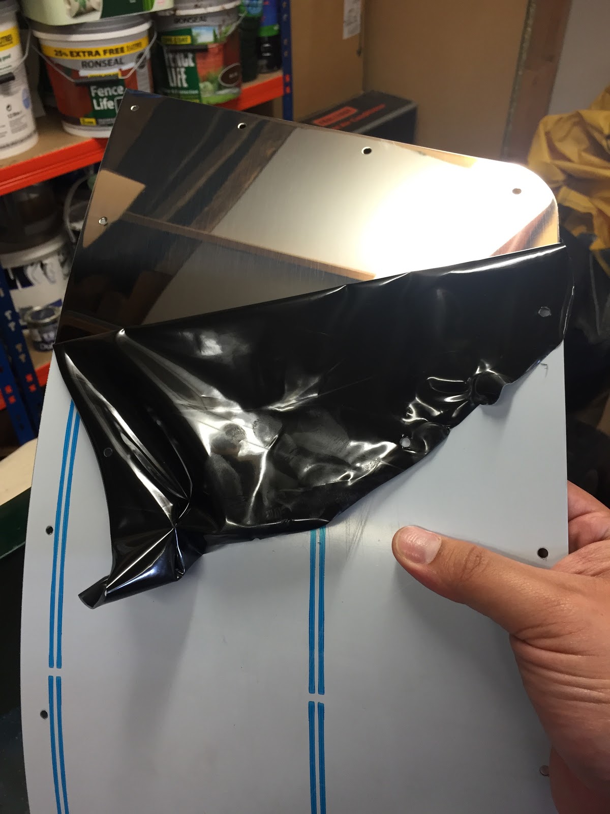
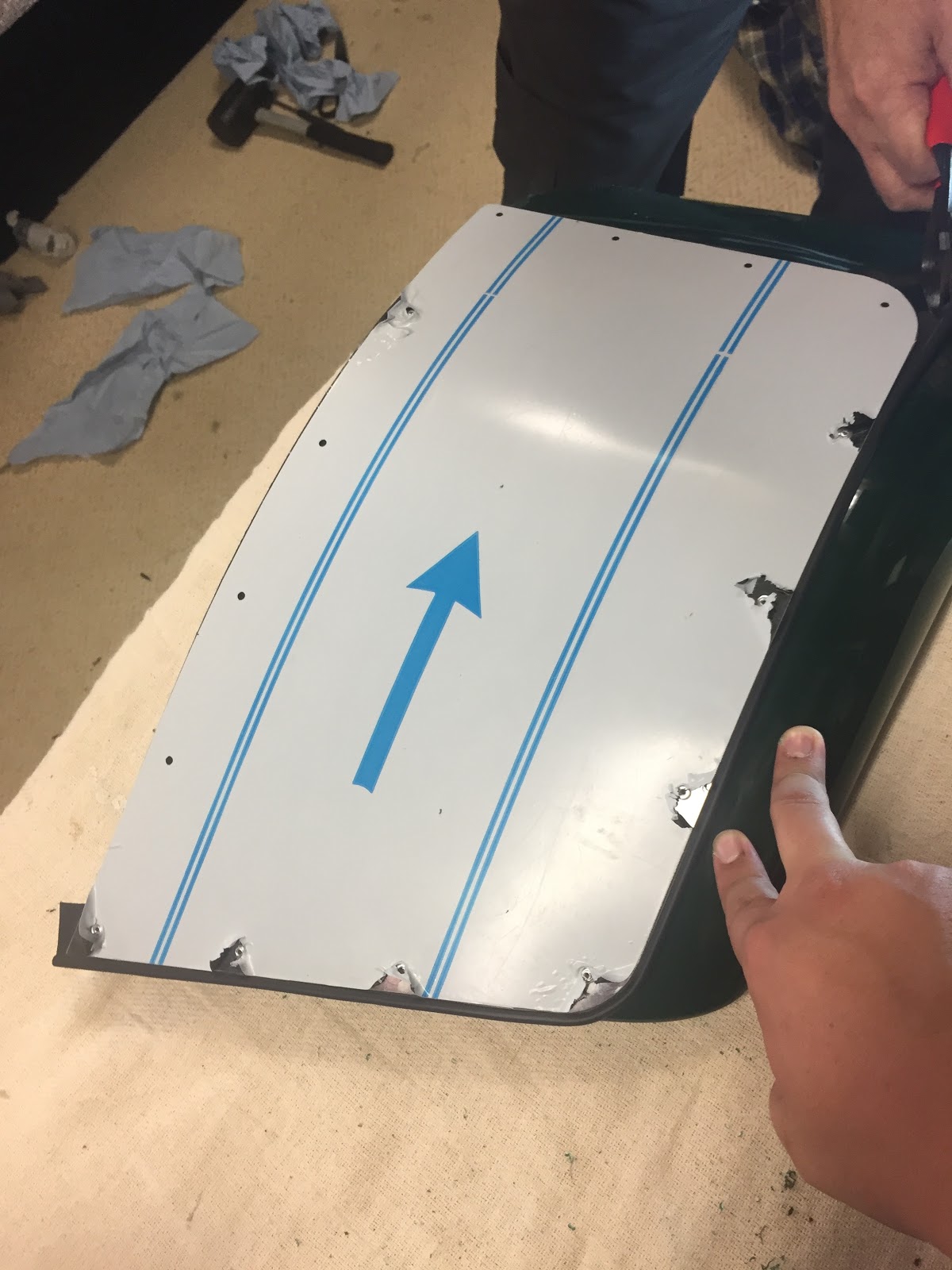
Missing packet of Rear Wing fixings
Firstly Derek had sent the missing packet of fixings for the rear mudguards, including the necessary roll of the rubber 'P' Seal (see above), so we spent some time investigating how these all go together (as you'll see below), certainly cleared up a few unanswered questions we had regarding the rear mud guards and the stone guards.

Contact adhesive; recommend masking off and then using spray contact adhesive. Note the cross-member.
The first parts to be fitted today were the carpets on the sides of the transmission tunnel. We initially used a mixture of applied contact adhesive around the edges (see above) and the spray-type on both surfaces, however it became apparent that using just the spray can was much quicker and less messy.  However it can be messy if you aren't careful and we really recommend that you do a dry run first and work out how you are going to fit the carpet, paying particular attention to the notch for the cross-member (again see above) and the holes for the harness/seat belt mounting points. Contact adhesive is entirely that; it sticks on contact! It's also worth masking the edges to keep things cleaner, however any over-spray was easily wiped up with a rag dipped in a very small amount of Xylene thinners.

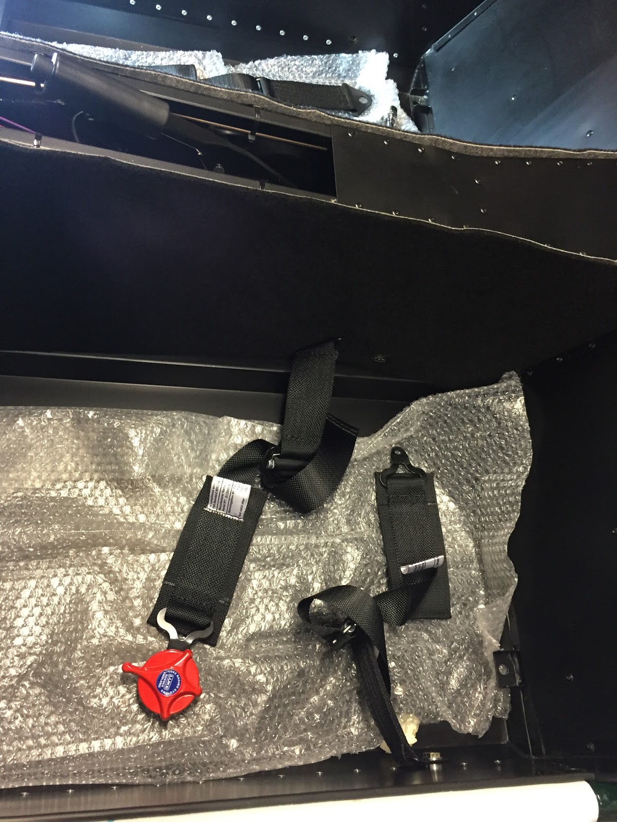
Side carpet & passenger harness lap belt fitted. Note; red buckle is fitted inboard and therefore harnesses are handed.
Next we fitted the lap belt part of the 4-point harness, however we had a problem; there are two possible threaded holes on either side of the transmission tunnel, fore and aft. The Assembly Guide shows that the inboard side uses the forward hole, in keeping with the indentation on the side of the transmission tunnel which is, I guess, for seat belts. However the aft hole of the one that we used is similarly threaded and also directly opposite the outboard mounting point, so why wouldn't you use this? However if this is wrong it's an easy fix to move the mounting point backwards if required. Also it is important to note that the harnesses are handed, the quick release (red buckle) is always fitted to the inboard side of the car and the red release catch points to the floor.

Assembly Guide says to mount the inboard lap harness to the front hole, so what's the rearmost hole for?

We worked out where we are going to fit the poppers/dot fasteners on the rubber mats to stop any migration towards the pedal box, so that they don't interfere with the free movement of the pedals. However from the test fit it looks like we'll have to trim the rubber at the sides, as they're a little too wide at present.

Also worked out the interaction of the boot cover and how it fits with the hood sticks and the shoulder harness (had no idea the hood-sticks went under the boot cover, oops), they'll be fitted another time. It's going to be fun trying to measure and fit the poppers/dot fasteners...

Fitting leather seats; bases come off, easier job than we thought. It's worth extra greasing of the runners though.
A job we thought that was going to be difficult but turned out to be a lot easier was the fitment of the seats (above), the base comes off so it's a cinch fitting them. However, before fitting the seats it's worth working in some more grease into the runners, ours weren't really running that freely to begin with. Although some grease had already been applied on ours they were still rather stiff, so we worked some more in by running them back and forth a few times. Also when were adding the washers and nyloc nuts underneath the floor we used a small bead of black silicone sealant around the bolt holes, which then got squeezed as they were tightened. This was to help stop any water ingress from through the floor.

Seats and Harnesses fitted, just have to fit the tunnel top, leave that to later on.
In fitting the cycle wings the assembly guide suggests drilling through the wing-stays and fitting using the bolts supplied. However, from looking at numerous other Sevens, most people seem to stick their cycle wings on (including even factory built Sevens?), plus it looks a lot nicer!

Initial bead of Sikaflex applied to cycle wing
Firstly we fitted the IVA rubber strip around the outside of the cycle wings, there's a long and short side, the short side was used as the long side would have interfered with where the repeater light sits on the wing, plus it aesthetically it looks better. Next, Dad attached some masking tape to the wing & stay and adjusted the wings so that we had 80mm from the centreline of the front wing-stay to the edge of the front of the cycle wing. He then marked a line so that we would have a datum to come back to once we applied the adhesive. The adhesive we used was Sikaflex 255 (black windscreen adhesive), recommended by the Caterham group on Facebook. Firstly we added a bead on top of the wing-stay (see above) and carefully placed the cycle wing on top, paying particular regard to the markings made previously. We let that dry for an hour or two whilst working on the rear mudguards and then added fillets of more adhesive on each side of each wing-stay.

Wing stuck on prior to adding of more adhesive.
Before we ran out of time we started work on the rear mudguards, we started by test fitting them to the side of the car and then adding the 'P' seal so we could mark out where to stamp out the holes for the bolts. We also had to do a little enlarging and fettling of the hole for the radius arm by using a file (use appropriate protection here, GRP fibres can be nasty stuff!). From research of other blogs, some people cut a slot in the wing however we thought it would be good to preserve a little more strength and rigidity by enlarging the hole, however it is rather time consuming.

That's it for now, off to the cinema for date night with the wife!

Thursday, June 30, 2016

De Dion and Rear Suspension fitted

Rear suspension and De Dion fitted in my absence.
I can't say too much about the events here owing to Dad working on the car on his own, but he has achieved a lot! In two days he's managed to fit the rear suspension and the De Dion tube on his own. Not only that, the brake line that required bending has been done, with no crimps (I believe it was bent around a largish socket to achieve this). Amazing when you have all the parts! 

Throttle cable and pedal arm.
Derek sent us the new throttle cable, however we're still not sure if it's correct. The pic you see above is after Dad was advised to bend the throttle pedal arm rearwards to achieve the correct range of movement of the throttle butterfly valve at the other end. However, coupled with the Assembly Guide picture suggesting routing of the cable around the top of the front of the engine it isn't quite long enough. The reason I say this is because the distance of the sheath between the clip mounted to the plenum (immediately below) and the plastic clip that goes through into the pedal box (further below) defines this length. This says to us that the sheath on the cable is too short and bending the throttle pedal arm is a bit of a cheat. We're going to leave as is for now and take further advice.

Clip onto the plenum
Clip passing through into the pedal box
 One of the outstanding issues is the routing of the lambda sensor wiring to the loom. We're not liking the idea of having to drill holes in the front of the square tubing at the base of the pedal box (shown below, just above the line of rivets covered by the silver heat shielding). This is because of the potential for water to ingress and rot the tubing out from the inside. We'll have to take advice on that however.

Lambda sensor, where to route the wiring?
The wiring for the oil pressure/temp sensor from the near the modine is rather long also, however we've been told that this is normal (probably to account for the dry sump system option?) and just to tie it up.


Oil (Pressure/Temp?) sensor wiring, loads of it, where to route it? Note the primer on the tubing, (scratched in the factory).
That's it for now! Hopefully my next post will include me helping with building the car...

Friday, June 10, 2016

A frustrating couple of days

Looking over the blog it's amazing how much time has passed since my last post and just how little physical progress we have achieved. This has been in part due to my work schedule being hectic (the busy summer season means it’s all hands to the pumps) - meaning I am away a lot and also in part our desire to work on the car together.

As such we've taken the decision that Dad is going to have to come over and build the car without me on some days. I’ll muck-in where I can when I’m at home but it’ll be hit and miss whether I’ll always be there to work the car. It’s a real shame as we’ve had a lot of fun so far doing the build and has been great as a Father/Son bonding exercise, as well as some good banter. However we are where we are. If we’re ever going to finish the project we’ll have to pull our respective fingers out!

Whilst I was away Dad managed to start putting together the DeDion tube and it’s fixings, one thing you’ll note from the picture below is the right hand brake tube doesn’t fit into the hole in the brake calipers (however the left side is bent correctly). We’ll have to bend the tube to the correct shape without kinking it; I’m sure my father’s tin-smithing skills are up to the job!

Going to have to bend the brake line to fit into the caliper (red plug). Fun.
He has also fitted the brake lever 

Handbrake fitted
And the prop shaft.


One thing we’ve noted is that the new throttle cable that Derek has sent us still doesn’t seem to be right. The photos in the Assembly Guide show the throttle cable running around the front of the top of the engine, however this doesn’t do that, but also there’s a rather large amount of cable itself (90mm or so) unsheathed inside the pedal box (see picture below). Derek has assured us that we’ll need to bend the pedal arm in order for it to ensure the butterfly valve is fully open when you bury the accelerator pedal into the firewall. However we aren’t convinced, I’m sure that the sheath is too short, resulting in the issues with the cable’s routing and the amount of exposed cable in the pedal box. We shall have to see.

The final task of the day was to fit the rollover bar. We’ve gone for the FIA approved ‘X’ version and thought it would be a relatively easy thing to fit. However it had some problems fitting into the corresponding holes and mounting points on the chassis. We got it fitted, but only after some jiggling around and tightening some bolts to pull the frame into it’s correct place.

Rollover bar fitted; snug and surprisingly difficult to fit.


Thursday, May 12, 2016

Going backwards

Today we set out to once and for all to finish the engine bay, the cooling and electrical connections. It didn't happen, again! However we managed to go backwards, more on that in a bit.

Incorrect throttle cable
Firstly the throttle cable supplied is too short (see above), it's supposed to run from the pedal box on the left of the picture, around the front of the cam cover (off the bottom of the pic) and over the plenum chamber into the bracket and throttle body. However the one supplied barely reaches across the engine bay! Derek on the phone said it's more than likely that we've been supplied one for a K-series engine Caterham (the cool and hot sides of the engine are on opposite sides to a Ford Duratec engine, hence a shorter cable required). Anyways the new cable arrived a couple of days later and we'll fit that next time.

Coil Cover doesn't fit.
The second thing was the coil cover on the top of the engine not fitting (see above). Due to the new spec Ford Duratec now coming from Mexico the camshaft sensor (we think?) must be a different spec to the older Duratec and it protrudes up too far to fit under the cover. Derek again said that we need a new style cover; we have part no. 38E066A and we need part 'B', although I believe it's on back order, so that'll have to wait.

The offending article, camshaft sensor (?) too tall.
Moving onwards meant moving backwards, backwards in the car that is (See what I did there?)! It was time to start fitting the rear suspension and drive-train.  Firstly we laid out the main parts just to check we had everything.

Rear suspension parts laid out.
The assembly guide says to fit the handbrake assembly before attempting to fit the prop shaft and differential, however we couldn't find the clevis pins for the handbrake cable. That'll again have to be done later, however we did fit the handbrake cable.

Cap removed from rear of the gear box, ready for the prop shaft.
I don't think the Assembly Guide mentions it however we thought it best to fit the prop shaft first, good thing too, as once the Limited Slip Differential (LSD) is fitted it looks nigh on impossible to change or refit it! We put some gear oil on the splines of the prop shaft and it slid easily into the back of the gear box.

Prop shaft fitted.
Next was to fit the LSD itself, a rather heavy lump. Glad I had bought a new jack from SGS Engineering with a much bigger lifting height than my old one. Even so we still needed a couple of blocks of wood and some spare architraving nailed on top to stop the LSD from rocking around on the top of the jack, precarious!

Dad using some architrave to stop the LSD from rocking on top of the wood/jack stack, worked well.
Getting the diff in place took a while, getting angles and translations right using the jack, especially considering the jack raises in an arc. We had to raise, lower, then reposition a couple of times before we were happy to go for the final fitting, we also took the plywood boot floor (held in by a few PK screws) to get better access from above. Once we got the top brackets in position we used a couple of thick-ish Allan keys as a safety in case the wood or jack toppled over, at least it wouldn't then fall down. Then we managed to manipulate the LSD to align it with the lower mounts and get the bolts started in their respective threads (see picture below).

LSD in place atop the 'stack' of wood and jack, starting to shim. Note the Allan keys in the top mounts to make it safe.
The next task was to ensure that the diff was equidistant between the left and the right of the car. We had to measure between the same points on either side and then use the shim washers to ensure this would remain the case when the bolts were torqued up. It was a little fiddly getting the shims between the diff and the mounting brackets at times, but I'm pleased to say at the end of it we were less than 1/2 a mm out (and the bolts were lubricated with copper grease). I think we can be happy with that!

Looking up at the LSD from below the propshaft. Note the 3 shims used on the bottom right mounting bracket.
Once this was completed there was a rather long bolt that then went all the way through the top mounting, liberally coated with copper grease. The assembly guide mentioned about putting a chamfer on the end of the bolt (sharpening it a bit like a pencil if you will) to aid in fitting it through all the holes and shims, however this had already been done for us - useful. There was no measuring this time, the shims were just there to remove any potential play or movement of the LSD. Again a bit of a fiddly job holding the shim washers in place while you tap through the bolt with a rubber mallet, however this was soon accomplished.

All in all a decent days work. Nice to have big bits of metal fitted, still a little frustrating to have parts missing. However we still have plenty to do!